Master System 2 AV Mod
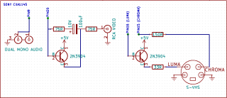
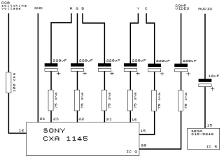
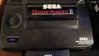
I picked up a Master System 2 cheaply and since it only supports RF as the video out I thought I would have a go at modding to support at least composite video out. The version I had used the Sony CXA1145 video chip. This seems to be a fairly common video chip found in a few consoles so it is well documented on what it does. On the SMS Power forums I found the following schematic:
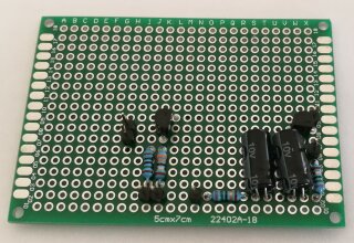
Using this schematic I decided to build this using a prototype board from AliExpress so that it would fit in the empty spot to the right of the Master System’s motherboard.
This worked nicely but to put in an external plug in it would involve drilling a hole into the case and I wanted to make this mod as clean as possible. To do this without making a new hole I removed the RF modulator as it has the worst video and sound quality of all the video outputs. Plus I won’t be using it anyway.
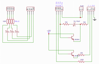
It was at this point I thought about designing a custom PCB for this. I don’t know if I happened to see an advert for it or just found it on Google but I came across JLCPCB where you can order a two layer PCB for $2 per 10 boards (plus shipping). Using the free online editor on EasyEDA I combined the above schematic with the RGB schematic by Mike Gordon (for RGB out and the switching voltage):
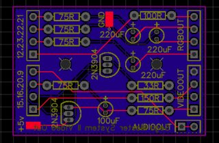
To produce a PCB design in EasyEDA. I hadn’t designed a PCB before but after a few hours I was able to design the following which will support RGB, RGB switching voltage, s-video, composite, audio:
I made the order along with the components from LCSC, they have a voucher for first orders and will combine it with the PCB order from JLCPCB, and then I waited for my order.
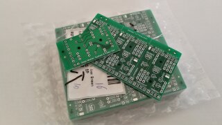
After a couple of weeks the parcel arrived. I now had 60 (six per sheet) PCB’s to play with (I didn’t plan on messing up that many times). I ordered a few different types of capacitors with various profiles in case some didn’t fit and to use the most of the voucher as I could :D.
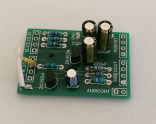
I quickly put one together to give it a test. Here I found the first design problem. The three capacitors for the RGB part are too close together, luckily I ordered the different capacitors with the narrower profile. These ones fit fine and the board worked fine (using composite).
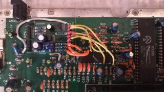
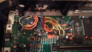
What I didn’t plan for was the PCB to fit perfectly where the RF modulator used to be, at this point I still had planned for it to go on the right hand side of the motherboard. If it would fit where the RF modulator lived then I wouldn’t have to run the wires as far. There was one small issue with doing this and this was the narrower capacitors were now a tad too tall so they hit the RF shield. To get around this I used the shorter but fatter capacitors but placed one on it’s side. Using some double sided sticky foam I stuck it to the motherboard and wired it up.
I designed the board so that it would use pin headers so that any connections I made could be disconnected without desoldering but since it is now where the RF modulator was it would have been better to have used pads instead of through holes (or use both) like the +5v and ground pads. It would have made wiring a bit easier.
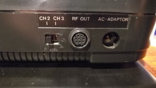
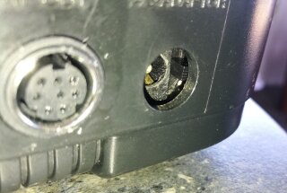
Since this board supports composite, duel mono audio, s-video and RGB I would need to have a plug that would fit all of these and fit in the RF out slot. AliExpress to the rescue again, I ordered a packet of 8 pin mini-din connectors. These were a near exact fit of the RF out slot, just a tad smaller (less than 1mm). I also picked up some slide toggle switches as I wanted to put a 50/60hz switch where the channel switch lived (this is a New Zealand PAL Master System 2).
Soldering the wires to the mini-din connector was a little frustrating but it wasn’t too difficult. You can see it here along side the 50/60hz switch:
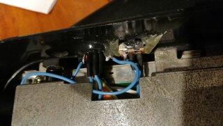
The ground connection I had wasn’t very good so I added another wire going from the ground pin/shielding of the mini-din and toggle switch to a washer that can be screwed down with the RF shield. Without this the image quality was poor as there was too much interference.
I epoxied in mini-din connector to give it some strength. The first photo shows the epoxy and the extra ground wire (blue wire between the switch and the mini-din). The second photo is what it looks like on the back of the system, the previous owner(s) were the ones that scratched around the channel switch slot for some reason.
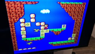
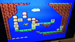
Overall I am pretty happy with the result, I can only test composite as I don’t have any display that supports S-Video or RGB. I do plan to make an adapter so that I can plug it into a GBS-8200 to convert the image to VGA but that is a future project. I now have 59 left over boards that I will use on future systems that I come across but if anyone is after one I am sure we can sort something out, you can find my contact details in the top menu. If you want to order some yourself, you can download the PCB in Gerber format. The screenshots below don’t show it as clear as it is.
Oh yeah, I also put in a blue power light.
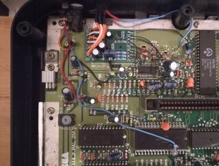
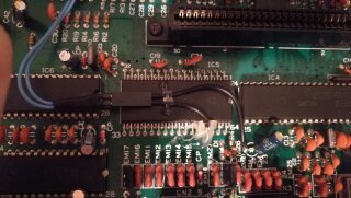
Update: This also works perfectly on a Master System 2 with a Fujitsu MB3514 video chip as it has the same pin out. It is more difficult as the pins are much smaller. Luckily there are a few alternate solder points nearby for some of the pins.
This Master System did not have a channel switch to place the 50/60hz switch in, so instead I placed it internally next to the power plug. When unplugged the switch can be toggled with a toothpick or tweezers. This way there is no damage to the case.
