Mega Drive II Modifications
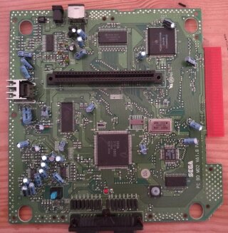
Following on from my 3D Glasses modification for the Master System 2 I wanted to see if I can add the 3D Glasses support to the Mega Drive. I have seen posts online asking if it could be done and the original Power Base Converter does support the 3D Glasses adaptor, so it should be possible.
Since I will be pairing up the Mega Drive 2 with an American 32x I need to also implement a 50/60hz and region modification using a single switch. On top of this I decided to install the Crystal Clear Audio board to enhance the Mega Drives audio.
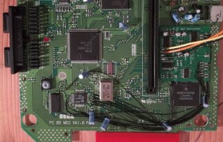
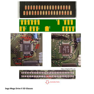
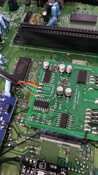
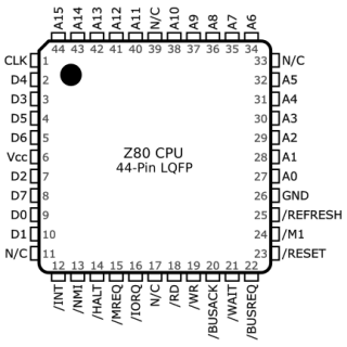
originally went with having the 3D Glasses board above the cartridge connector and threading the wires through one of the screw holes at the top to the underside of the cartridge connector. But I ran into issues with the wiring and the board was a bit too close to the cartridge connector. I was using the the pinout of the Mega Drive cartridge port found on Hardware Book combined with the Master System to Mega Drive mapping and the 3D Glasses pinout. This didn’t work correctly, likely due to getting the mapping incorrect rather than the pinouts so instead I went with wiring up the 3D Glasses board directly to the Z80 chip.
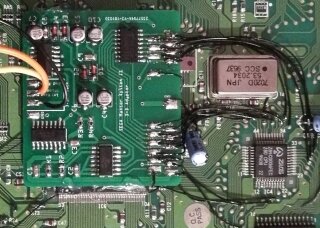
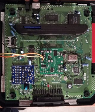
I found the pinout of the Z80 chip on the console5.com wiki. This can almost be directly mapped to pads on the 3D Glasses board except for the /M0-7 pad, for this I wired it directly to the cartridge port. Wiring it directly to the Z80 chip worked. I still had the 3D Glasses board above the cartridge port but was too close to the cartridge connector (and the wiring was messy) so I moved it closer to the Z80 chip. This kept the wire runs a lot shorter.
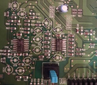
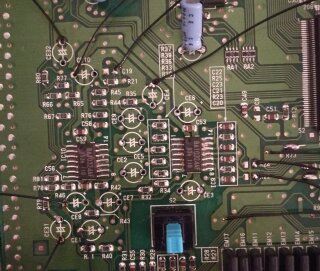
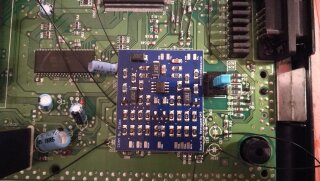
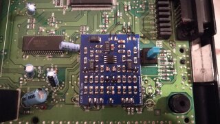
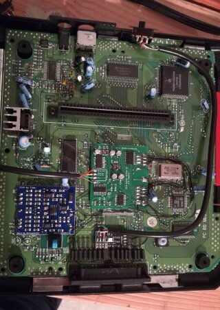
Next I installed the Crystal Clear Audio board. I wanted to make this tidy and didn’t have much space to mount the board I decide to try have place it in the same location as the capacitors that need to be removed. The way I did this was to remove all the capacitors and solder some wires to each of the required locations on the Mega Drive board. The wires were then angled outwards so that the CCAM board can be placed in the middle.
I used a dab of hot glue to place the audio board in the correct location and to keep it from resting directly on the Mega Drive board. Using the remaining capacitor near by and the power switch gave it a bit more stability. With the wire angled outwards I was able to then start routing the wires and clipping them short so that they were just the right length to reach the audio board.
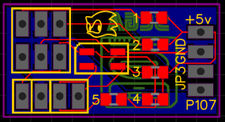
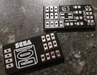
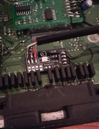
The last modification that I need to make is the 50/60hz and region switch. Reading this thread on assemblergames.com it describes how to set up a single switch to support PAL 50hz, NTSC 60hz and JAP 60hz along with a separate LED colour for each region using a couple of resistors. Again wanting to keep the modifications clean I decided to design a small circuit board that would use surface mount resistors and a tri-colour LED instead of three separate LEDs. Download the circuit board design.
As usual, I looked on AliExpress to find the components. I was originally going to use a 5mm tri-colour LED (common cathode) but at the last minute I saw the surface mount tri-colour LEDs and decided to include both a spot for the 5mm and the surface mount LEDs on my circuit board.
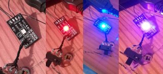
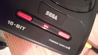
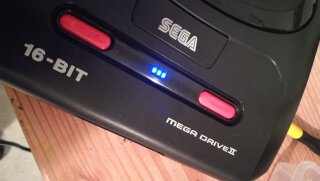
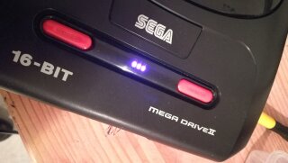
The board worked correctly except in two of the modes the colour of the LED (both LED form factors) looked almost identical. To fix this I removed one of the resistors (marked ‘5’ on the board) which resulted in the colours: blue, purple/violet and red. I could have played around with the resistor values, but I was happy with the three colours.
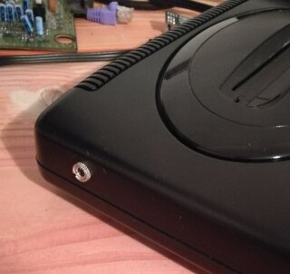
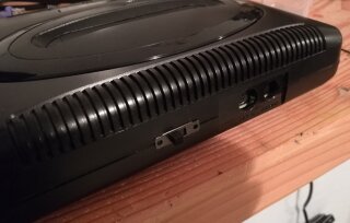
I removed the existing power LED and used a bit mounting tape to place it where the original power LED was. All that was left to do now was to mount the switch and the 3D Glasses jack. For the switch I decided to mount it at the back to the left of the power/AV port. I placed the 3D Glasses jack near the back left corner opposite where the Mega CD goes.
Parts Used
- Mega Drive II (PAL).
- Crystal Clear Audio Mod.
- 3D Glasses board or an original 3D Glasses board.
- Region board:
- Tri-colour LED (common cathode): surface mount or 5mm through-hole
- 3 Position DPDT switch
- 1k Ω 0805 surface mount resistors (these can vary to alter the LED colour and intensity)
- 3.5mm female stereo socket
